Full code checking member optimization can be applied to standard steel shapes based on the following codes:
The calculations performed encompass all the code requirements (including the local buckling criteria for slender compression elements in Appendix B of the 2nd, 3rd, and 9th Edition AISC codes) except those noted in the Limitations section of this document
How To Apply a Steel Design Code
Note:
The Hot Rolled Steel Design Parameters Spreadsheet records the design parameters for the steel code checks and may be accessed by selecting Members on the Spreadsheets menu and then selecting the Hot Rolled tab. These parameters are defined for each individual member and may also be assigned graphically. See Modifying Member Designto learn how to do this.
![]()
The following topics will discuss the steel design parameters by first discussing how it applies to regular prismatic steel sections. If the parameter is treated differently for Tapered WF shapes, that will be discussed separately in the Tapered Members section.
You may assign a unique Label to all of the members. Each label
must be unique, so if you try to enter the same label more than once you
will get an error message.
The member Shape or Section Set is reported in the second column. This value is listed for reference only and may not be edited as it is dictated by the entry in the Section/Shape column on the Primary tab.
The
See the Unbraced Lengths topic.
See the Unbraced Lengths topic.
See the Unbraced Lengths topic.
Cm Coefficients are described in Chapter H of the 9th Edition AISC (ASD) code. If these entries are left blank, they will be automatically calculated.
The Cm value is influenced by the sway condition of the member and is dependent on the member's end moments, which will change from one load combination to the next, so it may be a good idea to leave these entries blank.
Note
Cb Factors are described in Chapter F of the AISC code and are used in the calculation of the nominal flexural strength, Mn. If this entry is left blank, it will be calculated automatically for AISC code checks.
The calculation of Cb is based on the unbraced length of the compression flange and the moment diagram for the unbraced segment in question. If a specific unbraced length is entered by the user, the program cannot interpret the location of brace points and the Cb value will default to '1.0'. In some cases, it may be better to enter 'segment' as the unbraced length for a physical member. When 'segment' is entered, the Cb value will be calculated individually for each segment of the beam based on that segment's moment diagram.
Notes:
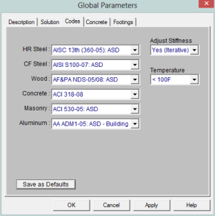
The Function entry may be set to either 'Lateral' or 'Gravity' using the drop down list in the spreadsheet. If the Adjust Stiffness option is set to Yes on the Codes tab of the Model Settings Dialog, then all members with a 'Lateral' Function will be considered for the stiffness reduction required per the AISC Direct Analysis Method.
The Flexural Stiffness Reduction of the Direct Analysis Method will be applied to all 'Lateral' members. This process involves evaluating certain conditions:
1. Primary Stiffness Adjustment Requirements: The program first checks whether a member satisfies the three primary stiffness adjustment requirements:
2. Stiffness Adjustment Calculation: Once the above conditions are met, the software proceeds to calculate the stiffness adjustments for the member. This includes reducing the area and moment of inertia based on predefined multiplication factors:
3. Exclusion Criteria: However, certain exclusion criteria are considered to determine whether to apply the stiffness adjustments or not. The following conditions must be met simultaneously for exclusion:
If all the exclusion criteria are met, the original area and moment of inertia values will be retained without applying the stiffness adjustment multiplication factors. This ensures that certain types of HR members, when using the AISC 13 code, maintain their original stiffness characteristics.
The program can perform an iterative analysis during the solution depending on the value of τb. In this case, the stiffness matrix is recomputed for each iteration until the value of τb converges within 1 percent for all 'Lateral' members in compression. In the unlikely event that τb is less than zero, the value of τb is considered to be 1.e-5. When used in the analysis, the value for τbwill be listed in the Detail Report for that member.
When the users sets the Adjust Stiffness flag on the
The Axial Stiffness Reduction of the Direct Analysis Method behaves differently. For the AISC 360-05, 360-10, and 360-16, the reduction will be applied to all 'Lateral' members.
Note
The type of connection for double channels is reported in the Channel Conn. column. This input is only for back to back channels and is used in the calculation of KL/r.
For double channels, the connector spacing ‘a’ is used in the calculation of KL/r. This input is only used for back to back channels.
Increasing of allowable stresses may be allowed when forces are transient. You may enter an ASIF factor on the Load Combinations Spreadsheet to allow the increase for a specific load combination. The ASIF factor is then applied to the allowable stresses in accordance with section A5. The ASIF factor also is applied to the Euler values (F'e).
Note
Setting the ASIF factor to a value greater than '1.0' will not cause the capacities to be increased by that factor. However, setting the ASIF factor to a value greater than '1.0' is used as a flag to use of the seismic compactness criteria of Table I-8-1 of AISC 341-05 Seismic Provisions of Steel Buildings. Specifically we will use the limiting width-thickness ratios from this table for capacity calculations (for compression flange local buckling for example). In these cases, we use Table I-8-1 of AISC 341-05 as opposed to Table B4.1 of AISC 360-05.
Wide Flanges:
Rectangular Tubes - Lateral torsional buckling is checked per section F7.4, however this section only applies to strong axis bending.
Code Checks - For combined bending and tension (Section H1.2) the code-allowed modification of Cb is not applied. For combined bending and compression, Section H1.3 is not considered, meaning that the program can be over conservative in some situations.
Single Angles - Single angles in compression are not checked for Section E4 because no standard single angle shapes have a slenderness (b/t) > 20. They are also not checked for Section E5 as there is insufficient information regarding the connections and usage of the member.
WT and LL Shapes - This code does not address the rare case where Lateral Torsional (or Flexural Torsional) Buckling occurs for WT's and double angles bent about their weak axis. Therefore, only yielding is checked for weak axis bending.
Double Channels -Double channel connector spacing requirements are not checked. Additionally, double channel design is only available in AISC 360-16 and AISC 360-10 codes.
Wide Flanges:
Code Checks - For combined bending and tension (Section H1.2) the code-allowed modification of Cb is not applied. For combined bending and compression, Section H1.3 is not considered, meaning that the program can be over conservative in some situations.
Single Angles - Single angles in compression are not checked for Section E4 because no standard single angle shapes have a slenderness (b/t) > 20. They are also not checked for Section E5 as there is insufficient information regarding the connections and usage of the member.
WT and LL Shapes:
Wide Flange Shapes - Code checks for shapes that qualify as plate girders, as defined by Chapter G, are not performed. Plate girders that can be checked by the provisions of Chapter F will have code checks calculated.
Channels - The AISC 9th Edition (ASD) specification does not specifically address the allowable stress for weak axis bending of channels. Therefore, the program uses the most similar formula for the weak axis bending of wide flanges (0.75*Fy). For a complete and thorough treatment of channel code checks, refer to the LRFD specification.
WT and LL Shapes - ASD allowable bending stresses calculated for WT and LL shapes use Chapter F for cases when the stem is in compression. This is not technically correct, but the ASD code does not provide direction regarding other means of calculating the allowable bending stress in this situation. In the interim, the LRFD code directly addresses this situation, so it is recommended that you use the LRFD code to check WT and LL shapes that have their stems in compression.
Neither the ASD or LRFD codes address the rare case where Lateral Torsional (or Flexural Torsional) Buckling occurs for WT's and double angles bent about their weak axis.
RE Shapes - Rectangular bar members (on-line shapes) are assigned allowable bending stresses for the yielding limit state only. Lateral torsional buckling is not considered because the ASD code doesn't directly address this for rectangular shapes. The strong axis bending stress is assigned as 0.66*Fy and the weak axis bending stress is assigned as 0.75*Fy. If you have a case where lateral torsional buckling may govern, you should use the LRFD code, since the LRFD code does address this limit state.
Wide Flange Shapes - LRFD code checks for shapes that qualify as plate girders as defined by Chapter G are not performed.
Single Angles - Single angles are only checked for Euler buckling. They are not checked for Flexural-Torsional buckling.
WT and LL Shapes - Neither the ASD or LRFD codes address the rare case where Lateral Torsional (or Flexural Torsional) Buckling occurs for WT's and double angles bent about their weak axis.
Tapered Wide Flanges - ASD 9th edition code checks can be performed on tapered members with equal or unequal top/bottom flanges, with the restriction that the compression flange area must be equal to or larger than the tension flange area. LRFD 2nd edition code checks are limited to tapered members with equal area flanges. Code checks are performed using Appendix F, Chapter F, and Chapter D as applicable. Note that the rate of taper is limited by Appendix F, and the program enforces this. The interaction equations in Appendix F are used to compute the final code check value. These equations also include the effects of weak axis bending, if present.
Prismatic Wide Flanges with Unequal Flanges - ASD code checks for prismatic WF members with unequal flanges are also limited to shapes that have the compression flange area equal to or larger than the tension flange area. LRFD code checks currently cannot be performed for prismatic WF members with unequal flanges.
Pipes and Bars - For pipes and round bars, the code check is calculated based on an SRSS summation of the y and z-axis stresses calculated for the pipe or bar. This is done because these circular shapes bend in a strictly uniaxial fashion and calculating the code check based on a biaxial procedure (as is done for all the other shapes) is overly conservative.
Single Angles - Code checking (LRFD or ASD) on single angle shapes is based on P/A (axial load/axial strength or axial stress/allowable axial stress) only. This is because the load eccentricity information needed for a meaningful bending calculation is not available. Only Euler buckling is considered for single angles, flexural-torsional buckling is NOT considered. Single angles will have the following message displayed on the Code Check Spreadsheet to remind the user of the axial only code check: "Code check based on z-z Axial ONLY"
Please see Single Angle Stresses for more information on the calculation of single angle stresses.
In some instances, code checks are not performed for a particular member. A message explaining why a code check is not possible will be listed instead of the code check value. You may click the cell that contains the message and look to the status bar to view the full message. The following are the messages that may be listed:
This message is displayed when the member is not defined with a database shape, a steel code is not specified on the Model Settings or no units were specified. For LRFD this message is displayed if the steel yield stress is less than 10ksi.
The ratio h/tw exceeds the limiting criteria listed in Table B5.1. This means Chapter G (plate girders) governs.
The axial compressive stress for the member is greater than the Euler buckling stress (per ASD criteria), meaning the member is unstable. A code check can not be calculated.
A tube is failing to meet the depth/width requirements laid out in Section F3-1 of the ASD code. The depth of the tube is the full nominal depth, which the width is taken as the full width minus 3 times the thickness. Section B5-1 specifies this calculation for the width when the fillet radius is not known.
This message appears for ASD code checking when Appendix B calculations are being done for a Tee or Channel shape and the shape fails to meet the requirements of Table A-B5.1, Limiting Proportions for Channels and Tees.
This message appears when Appendix B calculations are being done for a pipe shape and the diameter/thickness ratio exceeds the limit of 13000/Fy specified in Section B5-b for ASD, Section B5-3b for LRFD.
Section B7 recommends that KL/r for compression members
not exceed 200. For the ASD 9th edition code, a procedure is presented to handle
when KL/r exceeds 200. Thus, for ASD 9th edition, KL/r>200 is permitted. For all other AISC codes no guidance is provided as to what to do if KL/r>200, so exceeding this limit is not permitted.
The limitations of Appendix F for the design of web tapered members include the restriction that the flange area shall be constant along the length of the member. This member's flange area changes along its length. See Appendix Section F7.1 (b).
The limitations of Appendix F for the design of web tapered members include a limit on how steep the rate of taper can be along the member length. This member's taper rate exceeds the limit given by equation A-F7-1. See Appendix Section F7.1 (c).
The requirements for Wide Flange members with unequal flanges in the LRFD, Appendix F1, are not addressed.
The limitations of Appendix F for the design of web-tapered members include the restriction that the flange areas of the top and bottom flange must be equal. The compression flange may be larger than the tension flange. However equation A-F7-4 is unconservative for cases where the compression flange is smaller than the tension flange. See Appendix Sections F7.1 (b) and F7.4.
Parameters controlling the steel design are entered on the Member Design Parameters spreadsheet. These parameters are entered on a per member basis, and control the code checking on a per member basis.
w1 is the coefficient to determine equivalent uniform bending effect in beam-column, as described in Section 13.8.5 of CSA S16-09. If left blank, RISA-2D will calculate it. The w1 value is dependent on the member's end moments, which may change from one Load Combination to the next. Therefore it is a good idea to leave this entry blank and let RISA-2D calculate it.
w2 is the coefficient to account for increased moment resistance of a laterally unsupported doubly symmetric beam segment when subject to a moment gradient, as described in Section 13.6a of CSA S16-09. If left blank, RISA-2D will calculate it. The w2 value is dependent on the moment in the member, which may change from one Load Combination to the next. Therefore it is a good idea to leave this entry blank and let RISA-2D calculate it.
It is assumed the transverse load on the member is occurring through the member's shear center. This means secondary torsional moments that may occur if the load is not applied through the shear center are not considered.
Pipes and Bars - For pipes and round bars, the code check is calculated based on an SRSS summation of the y and z-axis stresses calculated for the pipe or bar. This is done because these circular shapes bend in a strictly uniaxial fashion and calculating the unity check based on a biaxial procedure (as is done for all the other shapes) is overly conservative.
Tapered Wide Flanges - No code checking is done for "Tapered WF" members which have different "Start" and "End" Depths, or which have top and bottom flanges of different widths. In other words, the "Tapered WF" may only be used for prismatic, doubly symmetric sections.
Single Angles - Single angles in compression are not checked for Clause 13.3.3.2 or 13.3.3.3 because there is insufficient information regarding the connections and usage of the member. They are not checked for Clause 13.3.2 (Flexural-Torsional Buckling) either. Instead they are checked for Euler Buckling about their geometric or principal axes per Clause 13.3.1. The slenderness classification for single angles is based on the longer leg.
S16-09 recommends using a "rational analysis" to account for lateral-torsional buckling and shear checks on single angles, so RISA uses the AISC 360-10 (14th Edition) provisions for these checks.
Class 4 Members - Members with both Class 4 (slender) webs and Class 4 (slender) flanges are not designed. Per S16-09, Clause 13.5.c.i these members must be designed per S136-07. Where only the web or the flange is Class 4 (slender) the capacity is determined per the provisions of S16-09, Clause 13.5c.
The code is not clear on whether this applies to WT, Double Angle, and Single Angle members, since they do not have a "web". Therefore, for these member types, the program calculates an effective (reduced) yield stress for each leg/flange/stem and uses the smallest value for the entire section.
Pipes and Round HSS - The code does not address how to determine the shear capacity of Class 3 or Class 4 (Noncompact, Slender) pipes. Therefore no design is done for those members. Class 1 and 2 member capacities are determined per the provisions of S16-09.
Shear Capacity - The code does not address how to determine the shear capacity of WTs, Double Angles, or Single Angles where shear buckling is a consideration (S16-09 Clause 13.4.3). Therefore no design is done for members where d/w or bel/t exceeds 1014/(Fy)1/2.
WTs - The lateral-torsional buckling moment capacity calculation (Clause 13.6e.i) in the code does not address how to calculate Lu when the stem of the WT is in compression. Therefore Lu is always taken as zero, which is conservative. The code also does not address how to calculate βx when the stem is in compression. Therefore, Iyc is taken as zero, which results in a negative value of βx, which is conservative.
Double Angles - The code does not address how to calculate lateral-torsional buckling moment capacity. RISA therefore uses the AISC 360-10 (14th Edition) provisions for these checks, as they are a widely accepted rational method. When this method is used, it is assumed that Cb = ω2. The slenderness classification for double angles is based on the longer leg.
Welded Reduced Flange (WRF) Members- Since these members are classified within RISA as "Tapered", there is currently no design done for them. This limitation will be removed in a future release.
Torsional Buckling and Flexural Torsional Buckling (S16-09 and earlier) - The limit states of torsional buckling and flexural torsional buckling are not considered for wide flange and channel members. This means that the value Fez is not calculated for these members per Clause 13.3.2. The program takes the lesser of Fex and Fexy for axial buckling capacity for the S16-09 and earlier codes. These limit states are fully considered for S16-14 because an Ltorque input was added for S16-14 that was not present in earlier code implementations.
Compressive Strength (S16-09 and earlier) - For the equations in section 13.3.1, the parameter "n” is assigned a value of 1.34 for all shapes for S16-09 and earlier codes. This is conservative for WWF shapes and HSS shapes that are stress-relieved. For S16-14, members designated as type "Tapered WF" use n = 2.24 while members designated as type "WF" use n = 1.34.
Double Channels - Double channel design for Canadian code is only available in S16-14. Connector spacing requirements are not checked for double channels.
WT and LL Shapes - The criteria in the AISC LRFD 2nd Edition code is used to perform code checks on WT and LL shapes since the Canadian code does not explicitly specify how to calculate the flexural strength of WT and LL shapes.
The Canadian code does not address the rare case where Lateral Torsional (or Flexural Torsional) Buckling occurs for WT's and double angles bent about their weak axis.
Tapered Wide Flanges - The AISC LRFD 2nd code is used to perform code checks on Tapered WF shapes when the Canadian code is specified. The Canadian code CAN/CSA S16.1-94 does not address web-tapered members.
Single Angles - Code checking on single angle shapes is performed for tension only. Single angles will have the following message displayed on the Steel Code Check Spreadsheet to remind the user of the tension only code check: "Single Angle code check based on Axial Tension ONLY"
Please see Single Angle Stresses for more information on the calculation of single angle stresses.
Slender Shapes - Shapes with any slender elements are not supported for axial compression. Shapes with slender webs or flanges are not supported for flexure. These shapes use the criteria in the CAN/CSA S136 code, which is not supported at this time.
When a code check is not performed for a particular member a message explaining why a code check is not possible will be listed instead of the code check value. You may click the cell that contains the message and look to the status bar to view the full message. Following are the messages that may be listed specifically for the Canadian Code:
The maximum L/r ratio for this tension member exceeds the limit shown in Section 10.2.2 of the CAN/CSA S16.1-94 code.
The maximum L/r ratio for this compression member exceeds the limit
shown in Section 10.2.1 of the CAN/CSA S16.1-94 code.
Compression strengths are not calculated for shapes that contain elements where the width to thickness ratios are classified as “slender”.
Flexural strengths are not calculated for shapes which have a web depth to thickness ratio classified as “slender”.
Flexural strengths are not calculated for shapes which have a flange width to thickness ratio classified as “slender”.
Compression strengths are not calculated for single angle members.
Parameters controlling the steel design are entered on the Member Design Parameters spreadsheet. These parameters are entered on a per member basis, and control the code checking on a per member basis.
Section 4.8.3.3.4 of the British code describes the m coefficient. If these entries are left blank, RISA will calculate them. The m value is influenced by the sway condition of the member and is dependent on the member's end moments, which will change from one Load Comb to the next. It's a good idea to leave these entries blank and let RISA calculate them.
This coefficient is discussed in Section 4.3.6.6 of the BS5950-1:2000 code and is used in the calculation of the flexural strength. If this entry is left blank it will be calculated automatically. This value also is impacted by the member's sway condition and is dependent on the member's end moments so it may be a good idea to let it be calculated internally. An exception to this would be for cantilever members in sway frames, this value should be 1.75, and it will be automatically calculated as 1.0. This will be addressed in a future program version.
It is assumed the transverse load on the member is occurring through the member's shear center. This means secondary torsional moments that may occur if the load is not applied through the shear center are not considered.
Tapered Members - Tapered WF shapes are done per the AISC LRFD 2nd specification at this time. The appropriate sections of the BS5950-1 specification will be used in a later release.
Torsional Warping Effects - Combined bending and warping torsional stresses in WF and Channel shapes are handled per the AISC publication "Torsional Analysis of Steel Members". A later release will use the SCI publication "Design of Members Subject to Combined Bending and Torsion" for combined bending and warping stresses when the British Hot Rolled Steel code is selected.
Single Angles - Single angles are checked for axial and shear forces only. No bending is considered at this time. A later release will consider the requirements in Annex I4 for single angles.
Secondary Moments per Annex I - The program does not yet consider the internal secondary moments described in Annex I.
Parameters controlling the steel design are entered on the Member Design Parameters spreadsheet. These parameters are entered on a per member basis, and control the code checking on a per member basis.
If these entries are left blank, RISA will calculate them per Annex B of the 2005/ 2014 EuroCode otherwise the user can choose to override the calculation by manually entering a value. The Cm value is influenced by the sway condition of the member and is dependent on the member's end moments, which will change from one Load Combination to the next. It's a good idea to leave these entries blank and let RISA calculate them.
For HSS Tubes, the program always uses Table B.1. For other members not subject to torsion deformations (wide flange members with an unbraced length equal to zero) the program will use Table B.1. for the 2014 code. All other members, the program will use table B.2.
If this entry is left blank, RISA will calculate it per Table B.3 in Annex B of the 2005 EuroCode, otherwise the user can choose to override the calculation by manually entering a value. The CmLT value is influenced by the sway condition of the member and is dependent on the member's end moments, which will change from one Load Combination to the next. It's a good idea to leave these entries blank and let RISA calculate them.
Section 5.5.4 (7) of the EuroCode describes the Bm coefficients. If these entries are left blank, RISA will calculate them. The Bm value is influenced by the sway condition of the member and is dependent on the member's end moments, which will change from one Load Comb to the next. It's a good idea to leave these entries blank and let RISA calculate them.
This coefficient is discussed in Section 5.5.4 (7) of the 1992 EuroCode code and is used in the calculation of the flexural strength. If this entry is left blank it will be calculated automatically. This value also is impacted by the member's sway condition and is dependent on the member's end moments so it may be a good idea to let it be calculated internally. An exception to this would be for cantilever members in sway frames, this value should be 1.75, and it will be automatically calculated as 1.0. This will be addressed in a future program version.
If this entry is left blank, RISA will calculate it per the explicit equation presented in the widely accepted article "Lateral-Torsional Buckling of Steel Beams: A General Expression for the Moment Gradient Factor" by López, Yong, and Serna (2006), as there is no suitable generic formula presented in the EuroCode.
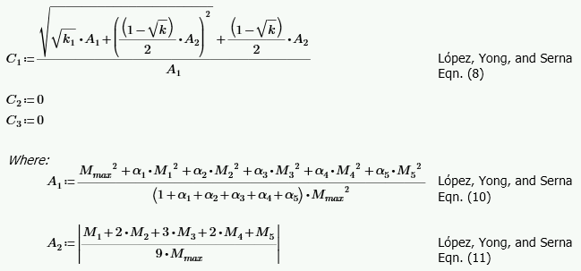
Otherwise the user can override this calculation by manually entering a value.
Note:
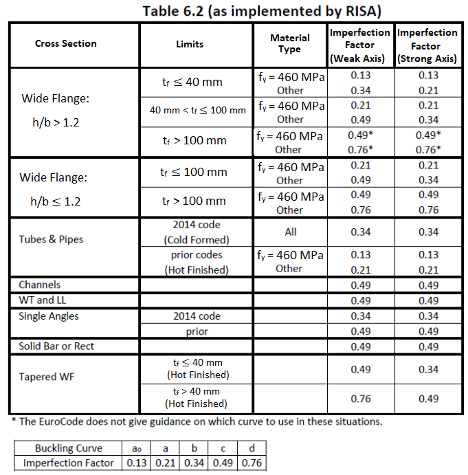
This factor is discussed in Section 6.3.1.2 of the 2014 EuroCode and is used in the calculation of the axial compression. Table 6.1 is used except for when Lateral Torsional Buckling is considered then Table 6.4 is used instead. The following illustrates what RISA uses for the buckling curve from Table 6.2:
Tapered Members - Tapered member design per the Eurocode is not supported at this time.
Torsional Warping Effects - Combined bending and warping torsional stresses in WF and Channel shapes are handled per the AISC publication "Design Guide #9- Torsional Analysis of Steel Members".
WT and Double Angle Limitations - The EuroCode does not address the rare case where Lateral Torsional (or Flexural Torsional) Buckling occurs for WT's and double angles bent about their weak axis. Therefore, the calculation of Mcr is based on AISC LRFD equation and used in the code checks for Lateral Torsional (or Flexural Torsional) Buckling.
Lateral Torsional Buckling - The value Mcr used in the lateral-torsional buckling capacity of beams relies on a factor C1. When the C1 field is left blank it is automatically calculated per the explicit equation presented in the widely accepted article "Lateral-Torsional Buckling of Steel Beams: A General Expression for the Moment Gradient Factor" by Lopéz, Yong, and Serna (2006),, as there is no suitable generic formula presented in the EuroCode. C2 and C3 are taken as zero because RISA relies on the "general case" lateral torsional buckling equations (see section 6.3.2.2) rather that the more specialized section for rolled and welded I shaped sections (6.3.2.3).
Single Angles - Single angles are checked for axial and shear forces only for EuroCodes. No bending is considered for Eurocodes.
In beams with high shear the code implements a moment strength reduction factor (ρ), but does not place an upper limit on it. If this value exceeds 1.0 the beam has a negative moment capacity, which is irrational. The program therefore prevents a code check for these circumstances.
Parameters controlling the steel design are entered on the Member Design Parameters spreadsheet. These parameters are entered on a per member basis, and control the code checking on a per member basis.
If these entries are left blank, RISA will calculate them. The m value is influenced by the sway condition of the member and is dependent on the member's end moments, which will change from one Load Comb to the next. It's a good idea to leave these entries blank and let RISA calculate them.
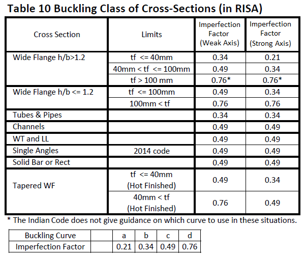
This factor is discussed in Section 7.1.2.2 of the 2007 Indian Design code and is used in the calculation of the axial compression. The following illustrates what RISA uses for the buckling curve from Table 7:
Tapered Members - Tapered WF shapes are done per the AISC ASD 9th (for the 1998 code) and LRFD 2nd (for the 2007 code) specifications at this time. The appropriate sections of the IS:800 specification will be used in a later release.
Torsional Warping Effects- Combined bending and warping torsional stresses in WF and Channel shapes are handled per the AISC publication "Torsional Analysis of Steel Members".
WT and Double Angle Limitations - The Indian code does not address the case where Lateral Torsional (or Flexural Torsional) Buckling occurs for WT's and double angles bent about their weak axis. For the 2007 code, RISA will use the AISC 360-05 (aka AISC 13th edtion) formulas for calculating member capacity for these failure states.
Shear Stress - For all shapes, the average shear stress is not checked per section 6.4.2 at this time.
Class 4 (Slender) Sections - No code checking is performed for class 4 sections for the IS 800: 2007 code.
Single Angles - Single angles are checked for axial and shear forces only. No bending is considered at this time.
Parameters controlling the steel design are entered on the Member Design Parameters spreadsheet. These parameters are entered on a per member basis, and control the code checking on a per member basis.
1. If this entry is left blank, RISA will calculate it based on the full length of the member.
2. When unbraced lengths (Lb_comp_top and Lb_comp_bot) are explicitly defined (enter a number), the program does not have the segmental information of the member for alpha_m calculation.
It will assume the alpha_ m used for this particular member to be 1.0.
3. When unbraced lengths (Lb_comp_top and Lb_comp_bot) are defined by physical nodes along the member with the entry ‘Segment’ typed in, alpha_m will be calculated automatically using equation 5.6.1.1(2) based on segments defined by nodes along the member.
The alpha_m value is influenced by the sway condition of the member and is dependent on the member's end moments, which will change from one Load Combination to the next.
Tapered Members - Tapered WF shapes are done per the AISC LRFD 3rd specification at this time. The appropriate sections of the ENV 1993-1-1 specification will be used in a later release.
Torsional Warping Effects- Combined bending and warping torsional stresses in WF and Channel shapes are handled per the AISC publication "Torsional Analysis of Steel Members".
WT and Double Angle Limitations - The NZ / AS codes do not address the rare case where Lateral Torsional (or Flexural Torsional) Buckling occurs for WT's and double angles bent about their weak axis.
Torsional Unbraced Length - At present the program assumes 'Lcomp' as 'Le' in case of lateral torsional buckling. Section 5.6.3 provides a procedure for calculating 'Le' which is not being addressed at this time.
Special Provisions for Cantilevers - At present the program does not address section 5.6.2 for cantilever elements.
Composite Steel Design - This is not done in RISA-
Welded Sections - There is a basic assumption in the program that the steel sections are hot rolled not welded. Therefore, any code provisions that assume additional stresses due to welding a built-up cross section are not specifically accounted for. For the AISC-LRFD codes this generally means that the flange residual stress (Fr) is always taken as 10ksi, as for a rolled shape. The only exception is for Tapered WF shapes where it is always taken as 16.5 ksi, as for a welded shape.
Load Location - For all shape types, it is assumed that the transverse load on the member is occurring through the member's shear center. This means secondary torsional moments that may occur if the load is not applied through the shear center are not considered.
Single Angles - In all codes other than AISC 360-05 and 360-10, single angles are only checked for axial loading. Flexural effects are not considered in the code check calculation. Under AISC 360-05 and 360-10 single angles are checked for combined bending and axial about either their principal or geometric axes depending on how their unbraced length has been defined.
Double Angles - For y axis buckling (where stitch connections would be experiencing shear), the program only considers KL/r of the overall built up shape and does NOT attempt to reduce the KL/r value based on the spacing between connectors. Therefore the program assumes that there are pre-tensioned bolts or welds spaced closely enough to allow the double-angles to act as one unit per AISC 360-10 Eqn E6-2a.
Net Section for Tension Capacity - The tension capacity is calculated using the Gross area. A later release will include a "net area factor" that the user can enter to indicate what the effective area should be for the tension capacity calculation.
Solid Rectangles - Solid rectangular members will not be checked for lateral torsional buckling. This limitation is only important for tall, slender shapes as LTB should not be a realistic limit state for short and thick or square shapes.
Torsional and Flexural Torsional Buckling of Doubly Symmetric Shapes - Flexural Torsional Buckling and Torsional Buckling are checked for the following shape types for AISC 360-10 (14th Edition) and AISC 360-16 (15th Edition) steel codes:
Flexural Torsional Buckling and Torsional Buckling are also checked for Non Slender WTs and Double Angles for the AISC 360-05 (13th Edition Steel Code).
For WTs (KL/r)m per section E4 (a) is calculated per equation E6-1 with 'a' always assumed to be 0. This results in (KL/r)m = (KL/r)o.
P-Little Delta Analysis - An incremental P-Delta re-iterative approach is used in RISA 3D. This method does NOT automatically account for P-Little Delta effects. If these effects are expected to be significant please refer to the P-Little Delta section.
The analysis for tapered wide flange members is handled internally by breaking the member into a series of 14 piecewise prismatic members. Then the program will condense out the extra degrees of freedom when assembling the stiffness matrix.
This does a very good job for member stiffness and basic analysis. However, because the extra degrees of freedom are eliminated before the analysis, it does not currently account for the P-Little Delta effect. If this effect is desired , please refer to the P-Little Delta topic for techniques to add this effect into your frame analysis.
These design specifications do not actually include any design provisions for tapered members. However, the AISC and MBMA jointly released Design Guide 25 - Frame Design Using Web-Tapered Members, which provides a design procedure consistent with the AISC design specifications.
RISA follows the recommendations of the Design Guide for tapered member codes checks whenever the AISC 13th, 14th, or 15th edition steel codes are selected.
The member detail reports will display not only the governing capacity values, but also the governing equations/limit state that provided the reported capacity. These limit states (and any design assumptions) are listed below:
In-Plane Flexural Buckling (z-z): The RISA implementation uses the Equivalent Moment of Inertia method described in Appendix A of Design Guide 25.
Out-of-Plane Flexural Buckling (y-y): This calculation uses the weak axis properties from the mid-section of the unbraced length.
TB (Torsional Buckling): Columns with equal flanges will only be checked for Torsional Buckling when the torsional unbraced length (K*L_torque) is greater than the weak axis buckling unbraced length (K*Lyy).
FTB (Torsional Buckling): RISA currently only checks flexural torsional buckling when the tapered member has unequal flange widths and (for cases when flange widths are equal) when the ratio of the flange thickness is greater than 1.5. This calculation uses the weak axis properties from the mid-section of the unbraced length.
LTB (Lateral Torsional Buckling): The RISA implementation uses the procedure for Single Linear Tapered Members for most members. In cases where both the thickness and depth of the way change, however, the program will use the more generalized procedure.
CAT (Constrained Axis Torsional Buckling): This is only checked when Lcomp-bottom is greater than Lcomp-top. The assumption is that the top flange is the outside flange and may be more restrained due to the presence of purlins or girts. The calculation of as and ac assume a girt or purlin depth of zero.
Combined Stress Equations: The RISA implementation uses the force based combined strength equations from chapter H1 of the AISC specification. The program does not consider the alternate stress based combined stress equations based on chapter H2 of the AISC specification.
Shear Strength: The shear check equations are based on section G2 of the AISC specification and do not consider the effects of stiffeners or tension field action.
Please see the Tapered Member results topic for more information about the results reporting.
Unbraced Length and Section Properties: When the user manually enters an unbraced length the program doesn't explicitly know where the brace points are and must make and assumption. This is done in order to determine the section properties at the middle of the unbraced length which are used in the calculation of member capacities. RISA assumes the brace points are equally spaced along the length of the member at the distance given by the user.
For example if the user entered in an unbraced length of 4 ft for a tapered member that is 10 ft long, the program will assume that there is bracing as 0ft, 4ft, 8ft and 10ft.
In general, this Design Guide allows for design of a wider range of members than permitted over the older AISC Appendix F provisions. However, there are still a number of limitations that will prevent RISA from reporting a code check. These are listed below:
Cb Calculation: Currently, RISA does not calculate Cb per Design Guide 25. Instead it is always calculated per the AISC 360 section F1 equation.
Tension Rupture: The tension rupture limit state is not considered.
Flange Qs Calculations: RISA will calculate a Qs value for both flanges and conservatively use the lower value in design calculations.
Direct Analysis Method: Currently, the Tau_b stiffness adjustments for the Direct Analysis Method is based on the worst case section in the tapered member. This worst case stiffness adjustment is applied to the whole member.
55 ksi Limit: The Design Guide includes a 55 ksi limit on maximum yield strength. If this is violated a code check will still be calculated, but a warning log message will be given.
For these design specifications, AISC included an Appendix F covering the design of tapered wide flange members. When calculating code checks per these provisions, the design parameters used in RISA are subject to the following additions / restrictions:
AutoCalc of K values:The K-out factor for Tapered WF shapes can be approximated by RISA-2D, and is the same as for a regular prismatic member. The K-in value cannot be approximated by RISA-2D and should be entered by the user. The default value for K-in will be '1.0' if not entered by the user. See the ASD or LRFD Commentary on Appendix F for an explanation of how to calculate the K-in factor for Tapered members.
Cb value:For Tapered WF members, the Cb field is actually used to enter the "B" value. B is described in Appendix F7.4 of the ASD (9th Edition) and LRFD (2nd & 3rd Edition) codes. This value is not calculated automatically and if it is left blank, a value of '1.0' will be used per the commentary for Appendix F7. The Cb term used in the Chapter F equations is calculated internally for Tapered WF members and will be shown on the Member Detail report and in the Code Check Spreadsheet.
Cm values: For Tapered WF members, the Cm values will be used for C'm. The C'm values are described in Appendix F7.6 of the ASD and LRFD codes. These terms are used in the interaction equations in Appendix F. If these entries are left blank they will be calculated automatically.
Canadian - w1: For Tapered WF members, the LRFD code will be used and the Cmyy(w1yy) value will be used for C'myy, and the Cmzz(w1zz) value will be used for C'mzz. The C'm values are described in Appendix F7.6 of the LRFD codes. These terms are used in the interaction equations in Appendix F for the LRFD code. If these entries are left blank RISAwill calculate them.
Canadian - w2: For Tapered WF members the LRFD code will be used and the w2 field is used for the “B” value. B is described in Appendix F7.4 of the LRFD codes. The Cb term used in the Chapter F equations in the LRFD code is always calculated internally for Tapered WF members and will be shown on the Member Detail report and in the Unity check spreadsheet. If the w2 entry is left blank a value of 1.0 will be used for B, per the commentary for Appendix F7. (The value of “B” is not calculated at this time.)
British - m: For Tapered WF members, the LRFD code will be used and the Cmyy(m_yy) value will be used for C'myy, and the Cmzz(m_zz) value will be used for C'mzz. The C'm values are described in Appendix F7.6 of the LRFD codes. These terms are used in the interaction equations in Appendix F for the LRFD code. If these entries are left blank RISA will calculate them.
British - m_LT - For Tapered WF members the LRFD code will be used and the m-LT field is used for the “B” value. B is described in Appendix F7.4 of the LRFD codes. The Cb term used in the Chapter F equations in the LRFD code is always calculated internally for Tapered WF members and will be shown on the Member Detail report and in the Unity check spreadsheet. If the m-LT entry is left blank a value of 1.0 will be used for B, per the commentary for Appendix F7. (The value of “B” is not calculated at this time.)
Euro Code - Cm/Bm: For Tapered WF members, the AISC LRFD 2nd Edition code is used and the Cmyy(m_yy) value will be used for C'myy, and the Cmzz(m_zz) value will be used for C'mzz. The C'm values are described in Appendix F7.6 of the LRFD codes. These terms are used in the interaction equations in Appendix F for the LRFD code. If these entries are left blank RISA will calculate them.
Euro Codes - Cm_LT / Bm_LT: For Tapered WF members the AISC LRFD 2nd Edition code is used and the m-LT field is used for the “B” value. B is described in Appendix F7.4 of the LRFD codes. The Cb term used in the Chapter F equations in the LRFD code is always calculated internally for Tapered WF members and will be shown on the Member Detail report and in the Unity check spreadsheet. If the m-LT entry is left blank a value of 1.0 will be used for B, per the commentary for Appendix F7. (The value of “B” is not calculated at this time.)
Indian Codes - Cm: For Tapered WF members, the LRFD code will be used and the Cmyy(m_yy) value will be used for C'myy, and the Cmzz(m_zz) value will be used for C'mzz. The C'm values are described in Appendix F7.6 of the LRFD codes. These terms are used in the interaction equations in Appendix F for the LRFD code. If these entries are left blank RISA will calculate them.